Ultrasonic Testing (UT) Fundamentals
You will learn how an ultrasonic testing (UT) probe sends sound into a component, why echoes appear on an A-scan, and what those echoes can and cannot tell you about hidden reflectors. Probe direction, component geometry, and material condition all matter before you interpret a signal as a possible flaw. This lesson focuses on conventional pulse-echo UT, not thickness calculations or acceptance decisions.
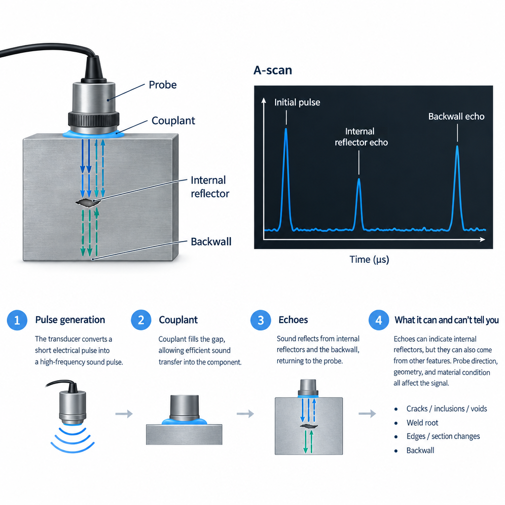
From sound pulse to returning echo
Inside the probe, a transducer changes a short electrical pulse into a high-frequency sound pulse. In pulse-echo UT, the probe sends sound into the component and receives returning sound. A couplant between the probe and component displaces air, which would otherwise prevent efficient sound transfer. Poor contact can make echoes weak or erratic.
When sound meets a boundary between regions with different acoustic properties, some energy may reflect. The far surface of a plate can produce a backwall echo. A crack, inclusion, or void may also return energy, but so can a weld root, an edge, or a change in section thickness. Not every reflector sends a detectable echo back to the probe.
What an A-scan shows
An A-scan displays received signal strength against travel time. Its horizontal axis may instead be set to show sound-path distance; either way, the position relates to the pulse’s journey out and back. The vertical axis shows echo amplitude—the strength of the received response—not the physical height of a flaw.
With a suitable straight-beam setup, a backwall echo may appear at a consistent position. An earlier echo could come from a reflector along the beam before it reaches that far surface. However, instrument settings, sound velocity in the material, and the beam’s path affect where signals appear. Horizontal position is not automatically a reflector’s depth, especially with an angled beam. A tall echo does not, by itself, prove that a reflector is large or rejectable: its orientation and shape can change how much sound returns.
The display is not a picture of the whole component. It represents responses from the sound paths sampled as you move the probe. If an expected backwall echo fades, the trace alone may not tell you why. Coupling, surface condition, material structure, or a reflector interrupting the beam could all contribute.
Beam direction and areas you may miss
A straight-beam probe sends sound roughly normal to the test surface. An angle-beam probe uses a wedge to direct sound obliquely, allowing an approach to a weld from beside it. Probe position and angle determine which part of the component the beam reaches; a clear response along one path does not clear the entire weld.
A flat, crack-like reflector often returns a stronger echo when the beam meets it favorably. If it is tilted so that reflected sound travels away from the probe, its response may be weak or absent. Beam width and spreading can also make location less precise, while echoes close together may be difficult to separate. Very shallow reflectors can be hidden in a near-surface dead zone, where the transmitted pulse and early responses interfere. Other inspection directions or techniques may improve coverage when the applicable procedure permits them.
Field example: an echo near a weld root
Suppose an angle-beam scan beside a pipeline girth weld produces an echo near the expected position of the weld root. The root profile or joint geometry could return sound, but an internal reflector might also be present. Calling the signal a crack because it is prominent—or dismissing it because it is near the root—would be unjustified.
Under the applicable procedure, you can note the probe position, scan direction, and how the echo changes as the probe moves. Compare its position with the known joint shape and the expected sound path, using other permitted scan directions where appropriate. A geometry-related response may recur at a predictable location, but repeatability alone does not prove its origin. If you cannot account for the response, preserve the location and setup information and seek qualified interpretation rather than assigning a flaw type or making an acceptance decision.
Material and access limits
Sound does not travel equally well through every component. Coarse-grained castings and some complex weld metals can scatter sound and mask smaller responses. A higher-frequency probe may help separate close echoes in suitable material, but scattering can reduce usable penetration. Rough or curved contact surfaces can make sound entry uneven. Edges and holes may create strong geometric echoes, while limited access can prevent the beam from reaching a region from the needed direction.
If coupling remains unstable, expected responses cannot be obtained, or the material makes echoes difficult to interpret, do not describe the examined area as clear without qualification. Follow the procedure for addressing or recording the limitation, and seek guidance from qualified personnel on how to assess the area.
Key Terms
- Transducer: The part of a probe that converts electrical energy to sound and returning sound to an electrical signal.
- Pulse-echo UT: A technique that sends sound pulses into a component and examines returning echoes.
- A-scan: A display of received echo amplitude against travel time or sound-path distance.
- Backwall echo: A return from the far surface of a component along the sound path.
- Angle-beam probe: A probe assembly that directs sound into a component at an oblique angle.
- Near-surface dead zone: A region close to sound entry where early responses can be difficult to distinguish.